

Center pitch is the distance between neighboring object centers. Edge gap is the clearance between their facing boundaries. For two unrotated rectangular bounds with widths A and B, horizontal gap equals pitch minus A/2 minus B/2. Equal numbers entered under different spacing definitions can create very different layouts.
The August 3, 2026 xTool Studio release notes explicitly distinguish edge-to-edge and center-to-center grid-array spacing. That software change highlights a practical design question for mixed-size batches. The arithmetic below applies to the layout itself; it does not claim that TYVOK software has xTool's controls.
Calculate the pair before duplicating the row
Imagine an 80 mm-wide tag beside a 100 mm-wide tag. At 110 mm center pitch, the horizontal gap is 110 − 40 − 50 = 20 mm. To obtain a hypothetical 12 mm design gap instead, use pitch 40 + 12 + 50 = 102 mm. These example clearances explain geometry; they are not recommended material spacing or thermal-process settings.
For identical 80 mm parts, that same 102 mm pitch leaves 22 mm between edges. Therefore, a fixed-pitch mixed-width row does not have a constant edge gap. If the order needs consistent visible spacing, calculate each neighboring pair or use a verified edge-based arrangement tool and measure its result.
| X1S Pro layout example | Calculation | Result |
|---|---|---|
| 80 and 100 mm widths, pitch 110 | 110 − 40 − 50 | 20 mm gap |
| 80 and 100 mm widths, desired gap 12 | 40 + 12 + 50 | 102 mm pitch |
| Two 80 mm widths, pitch 102 | 102 − 40 − 40 | 22 mm gap |
| Four 80 mm widths, three 12 mm gaps | 4 × 80 + 3 × 12 | 356 mm row |
Check what the bounding box includes
Select one complete part and inspect whether its measured width includes a decorative overhang, hole, or stray point. A distant stray point can enlarge the box even though the main outline looks compact. Rotated or irregular parts require actual boundary-clearance inspection; their bounding boxes alone may not describe the closest facing surfaces.
Keep internal holes attached to their intended part when rearranging. If nesting separates them, correct the relationship between outer shapes and inner cutouts before calculating the final panel extent. A spacious-looking row with displaced holes is not an acceptable layout.
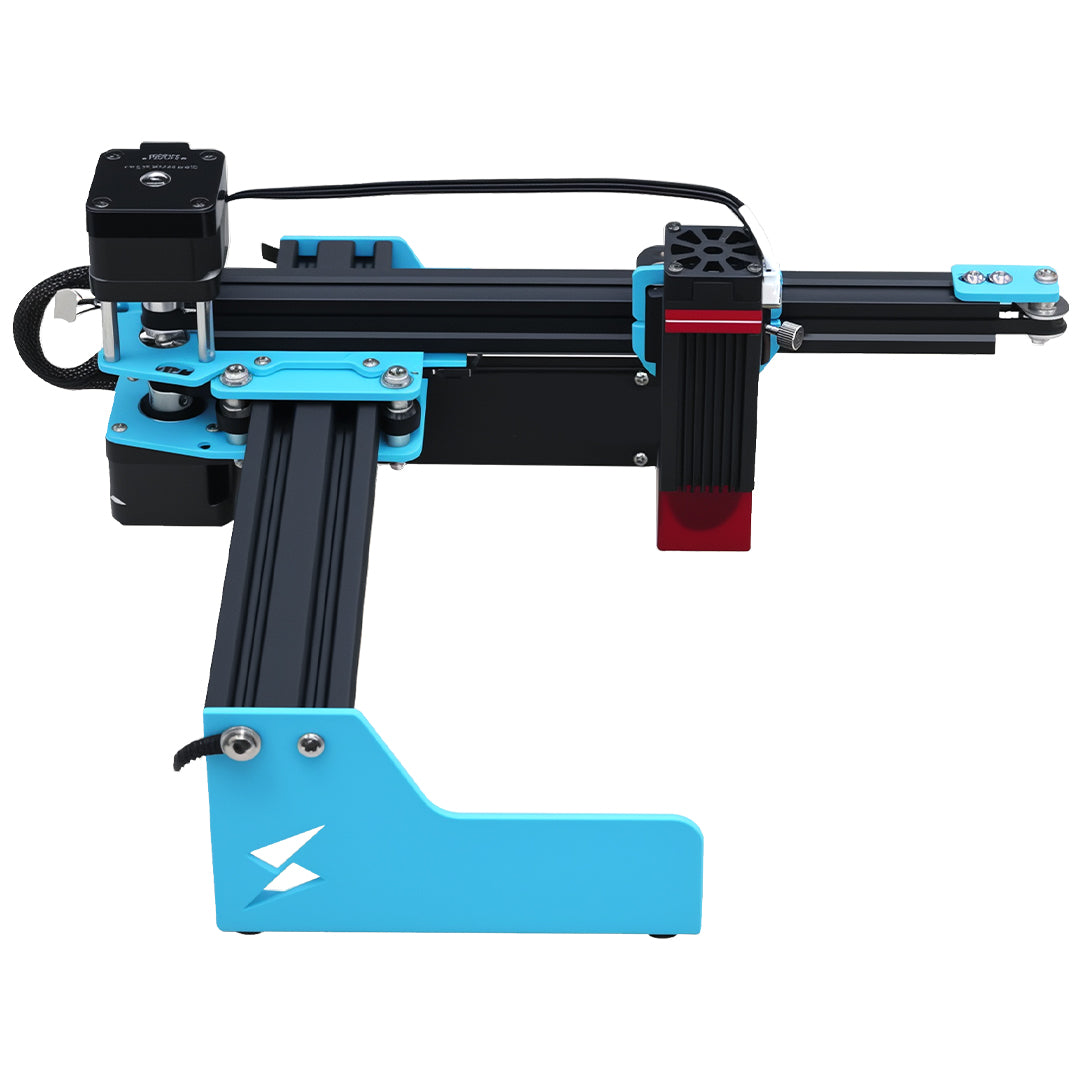
Measure the first pair, last pair, and overall row after duplication. Then compare that extent with the real usable material, fixture exclusions, and the configured machine workspace. The X1S Pro listing describes an 800 × 2000 mm format; a listed area is not permission to place material or motion through clamps or outside the supported setup.
Can center spacing describe the numbers around a square clock?
It describes distances, but conventional clock positions are governed by angles around the hand pivot. Use an angular square-clock layout when the labels must indicate time correctly. Uniform edge gaps around the square do not imply uniform hour angles.
Is a positive measured gap enough to approve the cutting layout?
No. It establishes separation in the artwork. Material behavior, toolpath offsets, holding requirements, and the validated process can require additional clearance. Select those requirements from the actual setup, then measure whether the layout meets them.